Agenda
In last article, we covered Introduction to various methods provided in Cisco SD-WAN to configure devices. Now we will explore Device Templates creation using Feature Templates. Here are some brief points before we start creating Device/Feature Templates.
- Feature Template: Cisco SD-WAN vManage GUI provides different templates for different features like VPN, System, Interfaces etc. These templates can be used by different devices types like ASR, ISR, Cat8k, vEdges etc. User need to select all platforms where a particular template is required. Also a single Feature Template can be used in multiple Device Templates. vManage GUI also contain some Factory default Feature templates which are based on Best practices and can be edited if required.
- Device Template: A Device template can be considered as a bouquet of multiple Feature Templates. A particular Device Template can be associated with a specific Device model. For different Device models different Device Templates are required.
Note, you would require to create different Feature Templates for vEdge vs cEdges as both have different Software/Hardware components.
Feature Templates Categories
On Cisco vManage, Feature Templates are categorized into 3 categories.
- BASIC INFORMATION Templates

- VPN related Templates

- Other Templates

Core Feature Templates
We had discussed on Core Feature Templates in last article. These Feature Templates are much required for a device operations. vManage GUI provides Factory Default templates for most Feature templates but for better management it’s recommended to tailor craft new Feature templates as per Network Design.
Site Topology
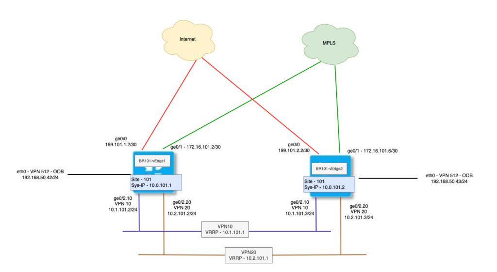
We will use below site topology to create Device Template using Feature Templates.

As depicted in above diagram, we have following requirements.
- Two vEdge routers, both having Internet (ge0/0) and MPLS (ge0/1) Circuits.
- Both Internet and MPLS circuits have Static IP addresses and default route to next hop.
- Interface eth0 in OOB – VPN512 and having static IP addressing.
- On LAN, we have two VPNs via ge0/2.10 and ge0/2.20
- VPN10 – Have VRRP for LAN Hosts.
- VPN20 – Have VRRP for LAN Hosts.
These routers are already on-boarded using CLI configuration. Let’s explore BR101-vEdge1 configuration and map it to different Feature Templates. Some of these configuration are default, so we wouldn’t need to create a Feature Templates for each. However, showing the mapping of each section of config as below.
System Template
system
 host-name               BR1-vEdge-1
 system-ip               10.0.101.1
 site-id                 101
 admin-tech-on-failure
 no route-consistency-check
 no vrrp-advt-with-phymac
 sp-organization-name    Controllers-150
 organization-name       Controllers-150
 clock timezone Asia/Kolkata
 console-baud-rate       9600
 vbond vbond
AAA Template
 aaa
  auth-order      local radius tacacs
  usergroup basic
   task system read write
   task interface read write
  !
  usergroup netadmin
  !
  usergroup operator
   task system read
   task interface read
   task policy read
   task routing read
   task security read
  !
  user admin
   password $6$Pq2aQg==$/LxJfuN3QNiPj5in7Z38VtZhwTDjPB81ZgT4Pbp7QJOsyxfjcHG1WhadUeCdW7NH5iGjTihFzOJV0ggdY/7pJ.
  !
  user admin1
   password $6$ajYsqw==$BevvXWCgebs5n8.Ffu.nRBSYS9kHAqzamXtTXrdk6JRCYXUAcoI3DFtUY7KC2lOEkAp6hwwLHbz1QuBlUgKzV1
   group    netadmin
  !
  ciscotacro-user true
  ciscotacrw-user true
Logging Template
logging
disk
enable
NTP Template
 ntp
  parent
   no enable
   stratum 5
  exit
  server 123.123.123.123
   version 4
   prefer
  exit
ZBFW Template
 support
  zbfw-tcp-finwait-time 30
  zbfw-tcp-idle-time    3600
  zbfw-tcp-synwait-time 30
  zbfw-udp-idle-time    30
OMP Template
omp
 no shutdown
 ecmp-limit       5
 graceful-restart
 advertise connected
 advertise static
Security Template
security
 ipsec
  integrity-type ip-udp-esp esp
VPN 0 Template
vpn 0
 name "Transport VPN"
 host vbond ip 150.100.1.3

 ip route 0.0.0.0/0 172.16.101.1
 ip route 0.0.0.0/0 199.101.1.1
VPN 0 – Internet Interface Template
 interface ge0/0
  ip address 199.101.1.2/30
  tunnel-interface
   encapsulation ipsec
   color biz-internet
   vmanage-connection-preference 6
   no allow-service bgp
   allow-service dhcp
   allow-service dns
   allow-service icmp
   no allow-service sshd
   no allow-service netconf
   allow-service ntp
   no allow-service ospf
   no allow-service stun
   allow-service https
  !
  no shutdown
VPN 0 – MPLS Interface Template
 interface ge0/1
  description "MPLS Interface"
  ip address 172.16.101.2/30
  tunnel-interface
   encapsulation ipsec
   color mpls restrict
   vmanage-connection-preference 4
   no allow-service bgp
   allow-service dhcp
   allow-service dns
   allow-service icmp
   no allow-service sshd
   no allow-service netconf
   no allow-service ntp
   no allow-service ospf
   no allow-service stun
   allow-service https
!
no shutdown
VPN 0 – LAN Physical Interface Template
 interface ge0/2
  mtu      1504
  no shutdown
VPN 10 Template
vpn 10
 name "Corporate LAN"
VPN 10 – Interface Template
 interface ge0/2.10
  ip address 10.1.101.2/24
  no shutdown
  vrrp 10
   priority 120
   ipv4 10.1.101.1
VPN 20 – Interface Template
vpn 20
 interface ge0/2.20
  ip address 10.2.101.2/24
  no shutdown
  vrrp 20
   priority 120
   ipv4 10.2.101.1
VPN 512 Template
vpn 512
 name MGMT-VPN

 ip route 0.0.0.0/0 192.168.50.1
VPN 512 – Interface Template
 interface eth0
  description "MGMT Interface"
  ip address 192.168.50.42/24
  no shutdown
Now let’s login to vManage GUI and navigate to Configuration > Templates > Feature Templates to create new Feature template. Here I am creating “System Template” as an example.
System Template
1. Click New Template under Feature Templates.

2. Search and Select required Devices models.

3. Select Cisco System under BASIC INFORMATION Templates. This will open a new System Template in edit mode.
4. Provide a unique name and good description. Both are mandatory fields.

5. Edit/Change the different variable options available. Note if you are choosing Device-Specific variable, try to give a good descriptive variable which will help assigning the values during template attach process. Here is snapshot as an example.

6. Save this template once done with changes.
Follow the same steps and create other templates as required. Initially it will take some time to create individual templates but since there are re-useable, you will observe significant time saving and other benefits of using Templates. I have created following templates as in below image.

Similarly, create other Feature Templates as required.
Create Device Template
Now let’s create a new Device Template to use these newly created Feature Templates.
1. Navigate to Configuration > Templates > Device Templates
2. Create Template and Select From Feature Template

3. Select Device Model, Role, Name and Description for Template.

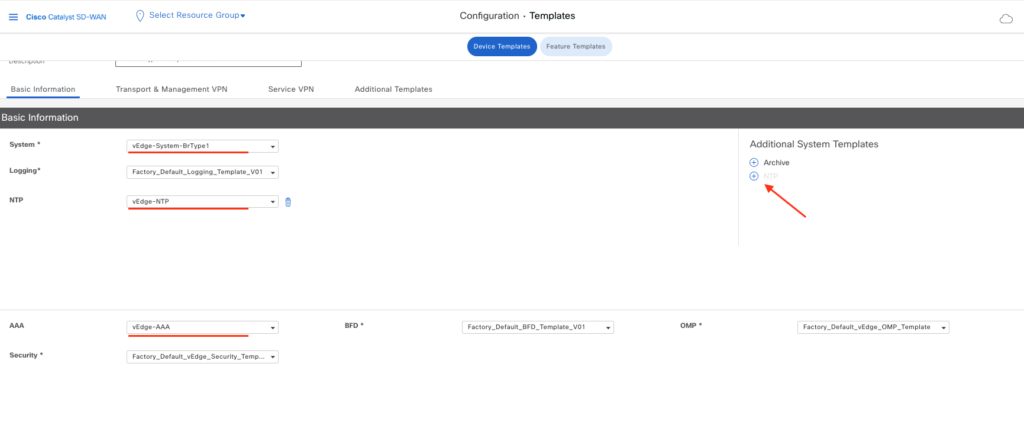
4. Select System, NTP and AAA Templates.

5. Select VPN0, Internet Interface, MPLS Interface, VPN512 and VPN512 Interface Templates.

6. Under Service VPN, select Add VPN to add Service side VPNs – 10, 20. This will open a new window.

7. Select VPN 10 and move to right.

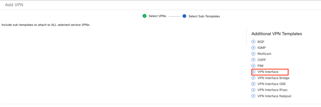
8. Click “VPN Interface” to add Interface to VPN 10

9. Select VPN10 Interface Template.

10. Repeat steps 6 to 10 and add VPN20 Feature Template/Interface.
11. Save the Device Template.
This completes creation of a New Device Template.
Attach Device/s to Device Template
Now we need to attach devices to this template to configure those devices.
1. Select options menu of Newly created Device Template and click Attach Devices.

2. Select the desired devices and move to right. Click Attach

3. On this screen we would need to provide Device Variable Values which we had specified in associated Feature Templates. We have two options here.
- Download variable csv file, update variables and upload here.
- Set variable values directly for each device.

Below is the filled csv file used in this article for reference.
4. Use either method and provide variable values for each device. Status will change to Green once all variables set. Click Next. (It advised to download the csv file once all variables are populated. That will help quickly add the variables if template push failure happens for any reason.)

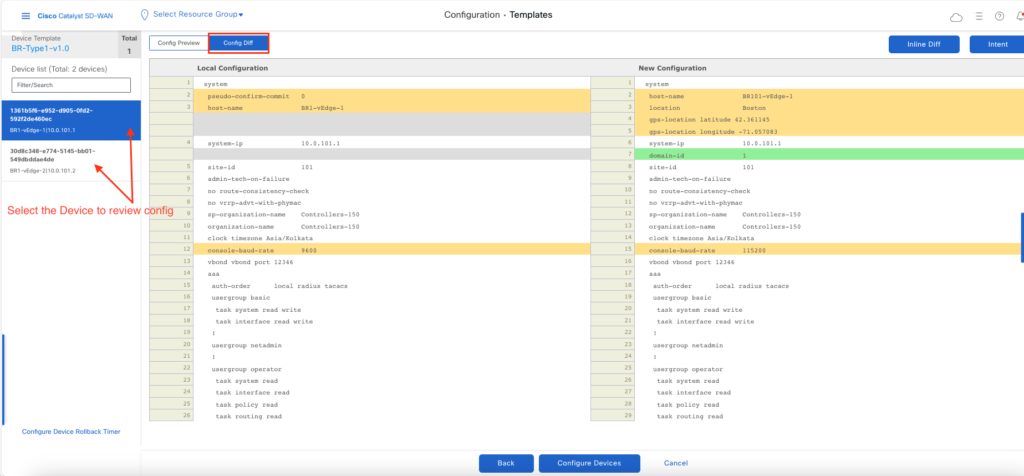
5. Click Configure to continue to next page. One next page, you can review the configuration of each device.

6. Now vManage will build the configuration from this template, compare with current config on router and prepare config diff. This config diff will then pushed/pulled to attached Edge routers. vManage GUI will present success/failure msg for this activity and template attach event can be reviewed.

7. You can check Template Name for each device via Configuration > Devices screen.

8. Edge router CLI output also reveal Template Name.
BR101-vEdge-1# show system status

<snip>
Personality:             vedge
Model name:              vedge-cloud
Services:                None
vManaged:                true               <<<<<<<
Commit pending:          true
Configuration template:  BR-Type1-v1.0      <<<<<<<<
Chassis serial number:   None
This Completes Demonstration of Configuring Devices using Device Templates. Happy Learning !!!
Further Reading: Cisco Catalyst SD-WAN Systems and Interfaces Configuration Guide, Cisco IOS XE Catalyst SD-WAN Release 17.x – Configure Devices [Cisco SD-WAN] – Cisco
